A VU meter or “Volume Unit” meter is a relatively straightforward device which provides a visual indication of how loud an audio signal is. They see use everywhere on devices such as mixers, microphones and sound systems; they provide a good way of warning the user that their audio may be approaching dangerous levels – or just clipping.
In this build, I will look at the principles behind a basic VU meter and then build it on a breadboard. I will hopefully make some improvements on the design as I go along as a few issues arrive when working on this device.
The basic sub-system, behind a VU meter is an ADC (analogue to digital converter), whose job it is to take an analogue signal on its input and produce a digital signal on its outputs that represents the amplitude of the input signal. There exist a number of different ADC circuits, but the one I will base my VU meter design around is a flash ADC (also sometimes referred to as a parallel ADC). A flash ADC in essence is simply a large ladder of comparators with a large resistor ladder to set the reference voltage for each comparator – this is not a very nice description and is better shown with a diagram, for the explanation, we will consider an ADC with only 4 comparators
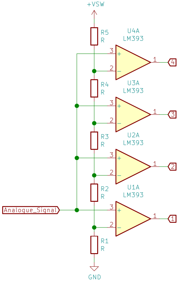
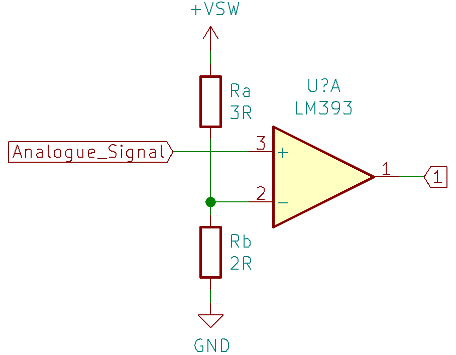
Here we have the input stage of a flash ADC, as you can see, it is just a large chain of comparators and resistors. You will notice that there are no values assigned for the resistors, only R – this is because the actual values are quite unimportant so long as they are they are all the same size (in my final design, this is not true for project specific reasons I explain later). You will also notice that I do not have an overflow comparator, which warns when the input signal has gone over the reference voltage – I did not want this for my VU meter as it would result in one output led that would likely never turn on – boring! So I instead added another resistor to make it so the final comparator reference is just below the reference voltage, such that it will likely turn on in normal operation. Lets look more closely at a single stage of this chain, namely comparator 1:
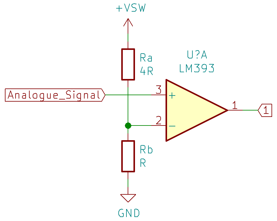
You will see I have simplified the resistor ladder greatly (series resistors Rt=R1+R2+Rn…) which will make it easier to work with. If we now work out the voltage that will be present as the inverting input as a fraction of the voltage supply, we can begin to analyse it
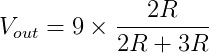
Now if we substitute in our values of Rb and Ra (where Rb is the resistance ‘above’ and Rb is the resistance ‘below’ Vout)
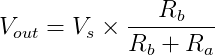
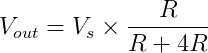
So this tells us that the reference voltage for comparator 1 is 1/5 of the reference voltage. So if we assume a reference voltage of 9v
Which equates to 1.8 Volts, so, now by regurgitating basic op amp action – the inverting input is always at the reference voltage of 1.8 volts. We will assume the analogue signal in began on 0 volts. The inverting input in this case is much much higher than the non-inverting input, so the output goes fully low. But then! the analogue signal suddenly rises to 2 volts! 2 volts is greater than 1.8 volts, so now the non-inverting input is greater than the inverting input and the output of comparator 1 goes high.
This principle continues up the chain of dividers, whereby, after the analogue signal rises enough, it will ‘beat’ the reference voltage of the next comparator and turn it on. Let’s (quickly) consider the next comparator up using the same process:
This time we have 3R above and 2R below
So this time, the reference voltage at the inverting input will be 3.6 Volts; this comparator will stay off until the analogue signal reaches 3.6 Volts or more in amplitude. Because of the nature of this circuit, if you know a comparator is on for certain, all of the ones ‘below’ it (with a lower reference voltage) must also be on – which is nice because it lets you skip a lot of horrible logic if you wish to convert the output to binary for example as certain states are impossible to attain e.g. comparator 3 will never be on unless comparators 1 and 2 are already on also.
Great, so now we have a nice bar graph like output to visually show the amplitude of an input analogue signal. Here is a demonstration in simulation:
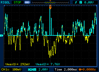
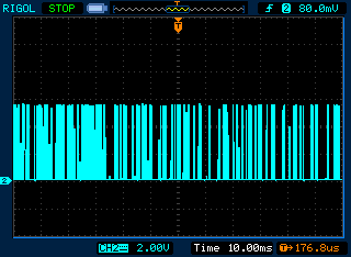
Next, we build. For my actual VU meter, I want it to take an input signal from my phone and feed this signal into the ADC; an important note about taking an input signal from your phone is that it will be a signal with both positive and negative voltages which requires additional circuitry to be able to work with properly, additional components I do not want to have to deal with for my basic VU meter, no thrills here. An example of an audio signal coming from my phone could look like:
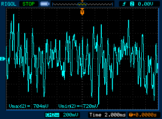
As you can see by the measurements taken in this time frame, the maximum voltage coming out of my phone was about 700mV and the minimum was about -700mV.
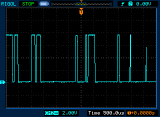
Because I only really care about the loudness of a signal, I think its safe to completely ignore the bottom half of the audio signal. Thankfully, this is easy to do, we can just supply the op-amps with only positive voltages e.g. +9v and 0v, this way I found that the negative going cycles are simply clipped off as the opamp simply cannot put its output low enough.
The first stage of this design is reading the input signal from my phone. Because I want to avoid drawing masses of current from my phone accidentally, I will first pass this signal through a non inverting amplifier stage with a gain of roughly 10 to create a more powerful copy of my phones signal, as it will be able to source more current as well as boosting the pathetic amplitude of my signal from ~1.5v peak to peak to a more respectable 15v (maximum) peak to peak. Note, because we are supplying the opamps with only 9 volts in my VU meter, it will never reach 15v, it will saturate – this is okay though, as you recall, we are not trying to preserve audio quality; we only care about its amplitude, so if a portion was going to clip, it was very loud anyway and the ADC will treat it as the loudest possible amplitude.
So the input stage for this VU meter looks as follows:
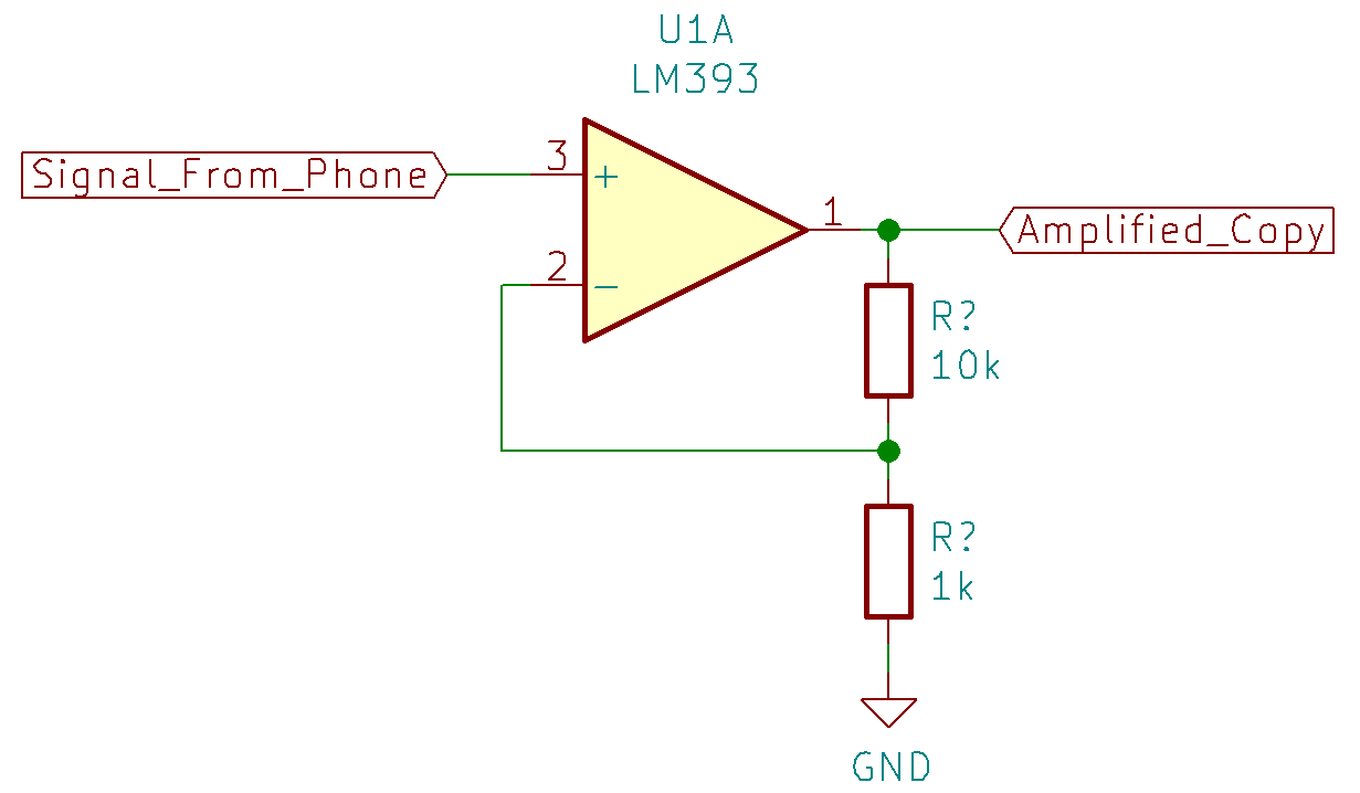
The output of this amplification stage removes the negative going waveforms as discussed, which provides a decent enough measure of how loud a signal is.
CONTINUE HERE WITH POSITIVE WAVEFORM THEN GO TO BOTTOM TO DISCUSS WHY LEDS ARE DIM DUE TO THE PWM LIKE EFFECT OF THE COMPARATORS AND SLEW OF THE OP AMPS!!!!!
We may then feed this amplified signal into the flash ADC which was discussed previously, the only difference here being that we want to have an ADC with 8 outputs for the VU indicator rather than the 4 previously – this is easy, we just add more comparators to the chain:
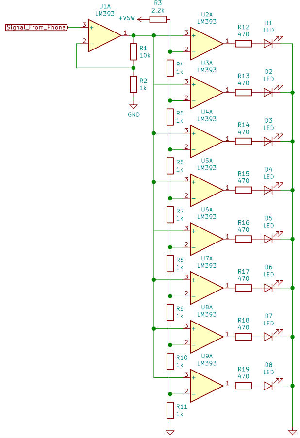
So this is the exact same design as before, only now with 8 comparators to allow for a more exciting output, I have also added the 8 LEDs with appropriate current limiting resistors. You may be wondering why R3 (the top resistor of the divider) is not the same as the rest of the chain (alluding to what I mentioned earlier about equally weighted resistors). During testing, I found that the signal would never get high enough for the last LED to ever turn on; rather than modifying the gain of the non inverting input stage, I decided it would be easier to just increase the resistance of the final resistor to lower the thresholds slightly for all of the comparators – this definitely did the trick.
So now the schematic is done, and I’m ready to build (this is a lie, I have been doing it as I go). Below is an image of the build in its current (not final) state:
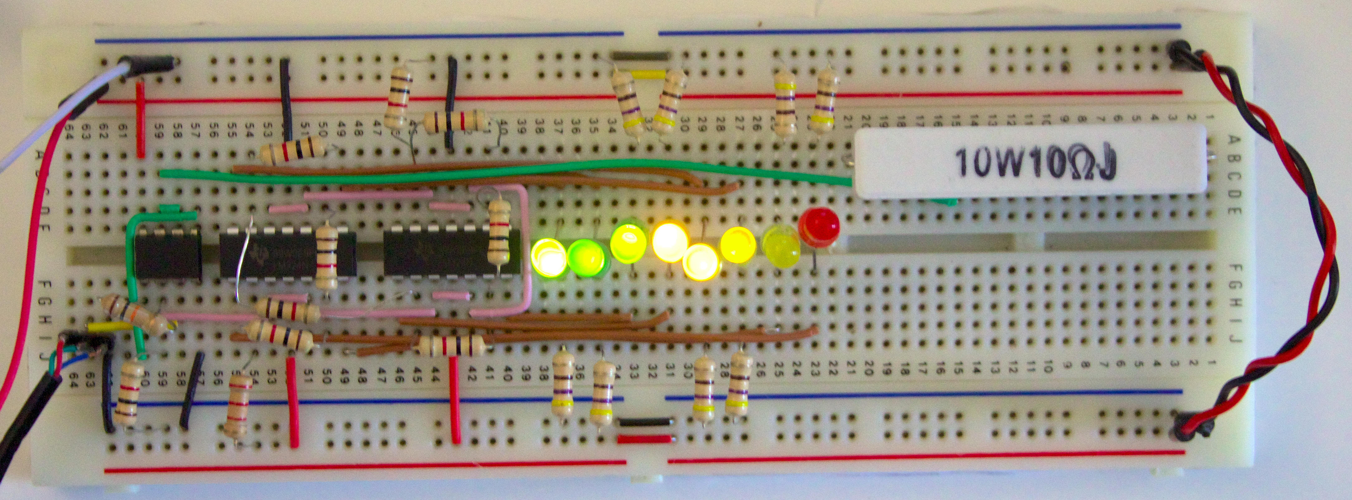
foe this build, I used an LM358 opamp for the input stage from my phone, just because I only need 1 opamp for the amplifier and this package has 2. I then used two LM324 quadruple op amp chips to construct the 8 comparator ladder. I also used different colour LEDs for more / less intense signal representations.

Remember how I said we don’t at all care about audio quality, well, we dont, this sub system would be added on the end of a proper amplifier. But it would still be fun to listen to the audio this thing it working with to quantify the loudness. Remember that we only have the positive portion of the audio signal.
So I used the additional opamp to make another follower to drive a small speaker that I do not care about (hence there being no high pass filtering) and wow wee does it sound absolutely awful:
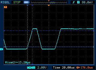
You can also see in that video that some LEDs appear to be very dim. This is caused by two factors: the incredibly responsive nature of a flash ADC and the slew rate of an the op amps in the comparator ladder. Particularly in that video we can see that the second from the left most LED is quite dim; lets attach a probe to it to see what is happening:
As the audio signal varies in intensity, each comparator (and hence each led) is turned on and off accordingly. The frequency at which this happens varies depending on the frequency spectrum of the audio, but it is generally quite high. As a result of this, we are inadvertently pule width modulating our LEDs which makes them appear much more dim than we might desire. You will also notice that in some cases, the comparator doesnt even turn fully on before it must turn off again due to the finite slew rate of the opamps (see the right most spike)
We could fix this by giving each LED some form of monostable filter such that when it is triggered it comes on for a fixed amount of time, or we could perhaps try adding some capacitance – each solution coming at the expense of accurate representation of the audio signals intensity (as LEDs linger on for longer then they should) as well as more components being required.
Next week I will look in more detail at the ADC and other alternate ADC options we have available to us.
